Sous-Vide Controller Part 2 – Building and Testing
I previously wrote about designing a temperature controller for sous-vide cooking. Here I will go through the process of building and testing the controller.
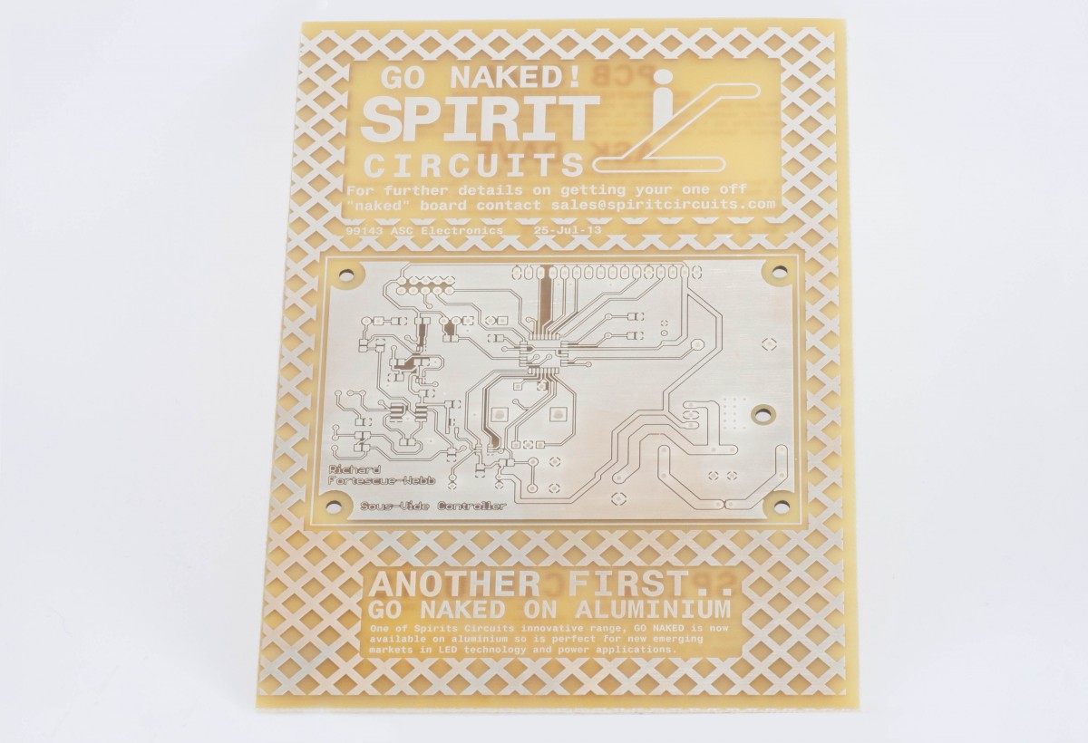
To produce the PCB I used a free service from Spirit Circuits in the UK. They allow customers to order three bare PCBs free before they have to buy anything, which is extremely useful for prototyping boards. I have a review on my blog here. The boards came out quite well although I did have a few problems with the design.
Circuit Issues
There were a number of small problems with the schematic which resulted in a few mod wires on the board. First of all, I neglected to properly read the datasheet for the ATmega168 and didn’t realise that the two extra pins on the surface mount package, ADC6 and ADC7, can only be used as analogue pins. This wasn’t a huge problem, I removed the buzzer and used one of the pins for the ADC as replacements, however it did mean that I didn’t have enough pins free to actually run the analogue temperature side.
In fact, the analogue temperature measurement side of the circuit was not without its own problems, I managed to order the wrong type of voltage reference to begin with which was solved by tying the reference pin of the ADC to +5V however the main problem concerned the current source. The PSSI2021SAY is a very simple current source consisting of a single PNP transistor and some diodes and resistors. As it turns out this doesn’t actually produce a particularly constant current source. For many applications this would probably be fine however in this case, I needed a current source that does not vary to any significant degree since the temperature calculation is based on the current through the thermistor. I actually measured variations over the range of about 15% which wasn’t really acceptable. It may be possible to calibrate out the variation in current but in the end I decided to scrap the analogue section and get everything working with the Dallas digital temperature sensor.
I also somehow inverted the input pins for the op-amps on the schematics so feedback was being applied to the non-inverting input. Trying to fix this with mod wires on a surface mount package was a huge pain and really made me reconsider ever doing very early stage prototyping with SMD components again.
Soldering and Heat Guns
For the most part, soldering all the components with an iron wasn’t really a problem, although solder-wick did turn out to be extremely useful for the tight pitch packages. I made one big mistake while putting the board together, I soldered the AVR in upside-down. I have no idea how I managed to do this, but after realising the problem I needed to remove the chip. Using a soldering iron and solder-wick really didn’t work, it’s impossible to get all of the solder out from beneath the pads. In the end I used a heat gun intended for stripping paint – obviously the wrong tool for the job but I haven’t yet appropriated a hot air soldering station. The heat gun actually works fairly well when used carefully, but even on its lowest setting, it is far too hot for soldering. Somehow the chip remained intact after removal and actually worked although I did scorch some of the plastic connectors on the board.
Once I had the chip oriented correctly, I started writing the software but I was still having problems programming the chip. As it turned out, the firmware on the old USBasp programmer I was using was corrupted. So with a new programmer I was making progress until the chip’s fuses were set incorrectly while programming. I’m not sure what they were set to but I it essentially bricked the chip (I did try a few clock sources but to no avail). Once again I needed to remove the chip. This time the heat gun was also fairly successful and with a new chip I continued writing code. At some point I ran out of space on the chip, I’m unsure exactly how this happened and haven’t really had a chance to look at the size of all the libraries I used but the program was now around 20 kB, too large for the 16 kB of flash on the ATmega168. Finally I decided to switch to an ATmega328 which is pin compatible. This time I was not so lucky with the heat gun, the board had been abused enough and I ended up with a lot of lifted pads and tracks. Eventually I solved all of these with mod wires or solder bridges but the solution wasn’t ideal.
Throughout the project I had numerous problems with the LCD connection. I used a simple ribbon cable to connect the LCD to the PCB and as you’d expect, when the board is moved around a fair bit, the weakest joint fatigues and breaks away. It is of course possible to solder these back on but it becomes somewhat difficult after a few breaks. If I were to do this board again, I would use IDC connectors for the LCD; although they add a remove a little space from the board, they make connections much simpler.
I hindsight, I definitely would have created the board with through-hole chips where possible, it makes removing and reworking everything far simpler, although I suppose that with a hot air station the board would likely have fared much better.
Construction
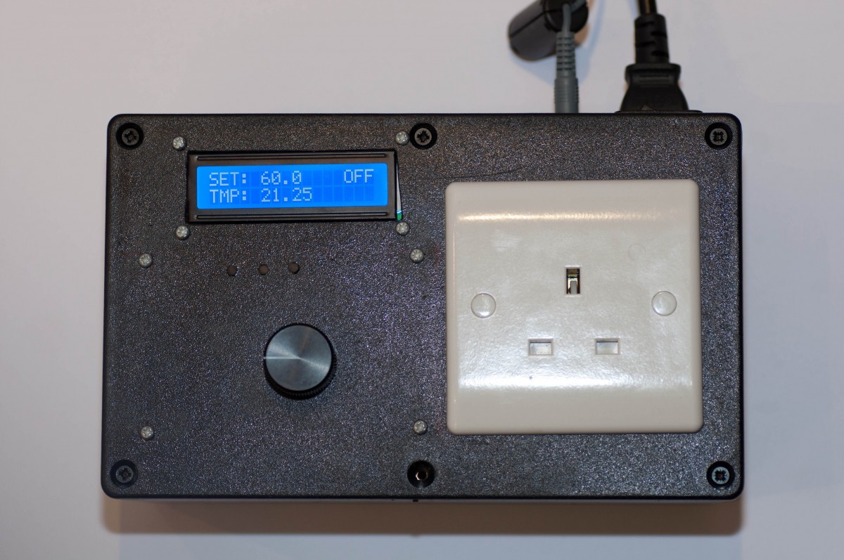
The PCB was mounted to the lid of the case using brass spacers, these were sized to place the light pipes directly above the SMD LEDs on the underside of the board. I was somewhat overzealous while filing out the hole for the LCD so there is a slight gap between the edge of the plastic and the LCD. The transformer and SSR were both mounted on the bottom of the box and their screws were earthed. I later realised that it would be a good idea to also earth reference the PCB just in case the live wire from the socket came free and contacted the board. The final version of the front panel looks like this:
I was somewhat worried that the SSR would get somewhat warm without a heatsink however with the low power of rice cookers and other heating elements that the controller would likely be used with, it wasn’t a problem at all. If a higher power element was used, it would be a good idea to add some sort of heatsink or at least some ventilation.
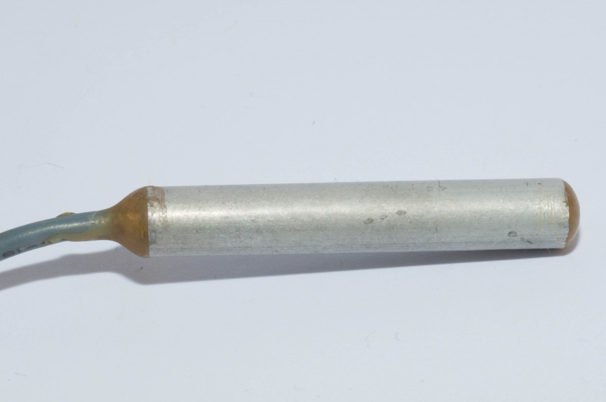
The temperature probe was designed to be connected via a stereo headphone jack (3.5mm). This allows headphone cables to be repurposed and gives the three connections required for the sensor (although the sensor can be powered from the data line, using a discrete power connection generally seems more reliable). The temperature sensor was soldered onto the leads from the headphone cable and insulated with heatshrink. Next, an aluminium tube was cut to size and filled with a little thermally conductive epoxy. This gives a reasonably good thermal connection to the sensor. Finally the tube was injected with normal epoxy (much less expensive) to fill the gaps and seal the ends. The final result is shown below:
During testing, I had some problems with interference on the temperature probe which caused the software to stop reading temperatures, although this was alleviated by using shielded cables to the PCB, there is still room for improvement.
The Next Version
Overall, I was fairly satisfied with the project. The main problem with the technique is that it lacks a circulator to redistribute the water around the vessel. This led to temperature differentials within the water bath of up to 4 °C which could be a real problem when cooking steak or something similar. For some reason, this didn’t really affect the results too much, the steak below was cooked at 55.5 °C for about one hour.

I will at some point produce another prototype, however I think I will move towards an immersion style heater, most likely built into a water bath with a circulator. Although this removes the possibility of using different size baths, I doubt I will ever need a huge amount of space, whatever is being cooked can generally be cut into pieces and done in batches if necessary. I will definitely use either a thermistor or RTD in the next version, although the final accuracy wouldn’t be that important, the resolution would probably be useful for the control algorithms. Also useful would be a quicker response time on the temperature sensor however this was much improved by using thermally conductive epoxy.
Another issue is the size of the controller. To fit everything on the front panel, I had to use a very large box, I think perhaps the best idea for miniaturizing it is to use a wall plug power meter case, like the kill-a-watt, but this means using some sort of reactive dropper or off-line switcher. I didn’t really want to be testing non isolated boards on the mains along with all the other electronics so I left this for a future version.
I have included most of the photos taken during the project in an album available here.