Sous-Vide Controller Part 1 – Design
Sous-vide cooking involves sealing food inside a bag (generally in a vacuum) and immersing the bag in a water bath at a carefully controlled temperature. Generally the water bath is kept at a fairly low temeperature – around 60 °C. By using such a low temperature it is possible to cook the item to an even temperature throughout, so a steak could be cooked to medium all the way through and then seared on the outside to give a result like the picture shown at the top of this page.
Currently, commercial sous-vide cookers are very expensive. Prices have come down over the past few years but the cheapest model on Amazon is still £126, somewhat more than I was willing to pay. So I decided to make my own version. While open source controllers do exist, like the ember kit, they are not easily available and I’d prefer to build my own anyway. The following roughly documents the design process of my controller.
Types of sous-vide cooker
There are currently two common methods of creating a sous-vide bath: immersion heaters and those with an element outside of the water container. Immersion heaters are generally portable and can be attached to any container which is a huge advantage if you ever need to cook a large item. Kickstarter has recently had two sous-vide controllers based on both methods, the Nomiku, an immersion heater and the Codlo, which allows any heating appliance like a rice cooker to be used as a water bath.
I eventually decided to build something like the Codlo, since it is far simpler to build and doesn’t really require the water in the bath to be circulated which would require something like an aquarium pump.
Box and Interface
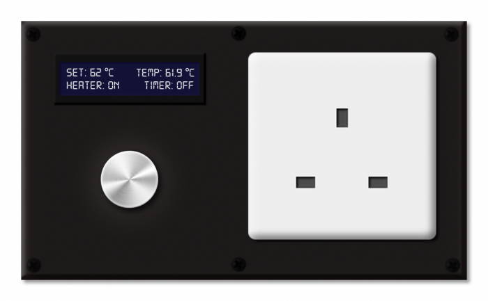
Having a plug-to-plug case something like the Codlo’s would be perfect however there’s nothing available like that and while it would be possible to make a box with both plug and socket, I decided in the end to just use a large ABS box from Maplin (the MB4 enclosure) and mount a socket on the top. The box is large enough to mount a mains socket on one side and an LCD and interface buttons on the other. While I was working out the dimensions I drew up a quick mock-up:
The LCD can be used to display the temperature and current state of the cooker. The only input is a rotary encoder, this allows the desired temperature to be adjusted easily and also includes a push-button. I’ve also included a timer function, this allows the controller to turn off the heater when the timer finishes and a buzzer will sound to let the user know when the food is done.
Temperature Sensor
One of the main objectives of any sous-vide controller is accurate temperature control and as such the choice of temperature sensor is key. I’ll quickly go over the four options.
First, and probably most popular is the K-type thermocouple. Thermocouples make use of the Seebeck effect to generate a voltage proportional to the temperature of their junctions, this voltage is normally in the mV range and must be amplified before digitizing. K-type probes are widely available and are not that hard to implement well however their inherent accuracy is not particularly high, it’s often quoted as ±1 °C and drift can become a problem.
RTDs (Resistance temperature detectors) – These devices generally have much higher accuracy than thermocouples, up to 0.01 °C apparently, however they are more expensive and require slightly more complex electronics.
Thermistors – Thermistors are essentially similar to RTDs in that their resistance varies with temperature. The difference is that the range of resistance over a small temperature range is much higher and accuracy can again be as high as 0.01 °C. Thermistors come in a number of varieties, differentiated by their resistance at 25 °C and their accuracy. One problem is that the temperature for a given resistance is not trivial to calculate, and some datasheets don’t actually list the required coefficients for accurate calculation.
Digital Temperature Sensors – Popularised by Maxim, these parts output a calibrated temperature accurate to within 0.5 °C on a one-wire bus. They are extremely easy to interface to and have high enough accuracy for most applications.
After some thought I eventually decided to use both a thermistor and a digital temperature sensor in my design, I wanted high accuracy and hence a thermistor seemed to be the best option (although I may change this to an RTD in the next prototype). The most common method for reading temperatures from a thermistor is to use a simple potential divider but this has fundamental issues and does not give very high accuracy. I used a slightly less common method of interfacing with the thermistor to achieve slightly higher accuracy. This is of course probably unnecessary. Although websites often state that super accuracy is the most important part of sous-vide, I can’t really see there being any problem with using a sensor accurate to 1 °C. That’s why I also included a digital sensor in my design, to make getting the basic control algorithms up and running a bit easier, and also just in case my thermistor circuit didn’t work (I didn’t have a chance to test it).
Circuit and PCB
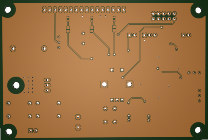
I recently came across a free PCB prototyping service from Spirit Circuits – their ‘GoNaked’ option. This allows you to produce three prototype PCBs with no soldermask or silkscreen for free before you buy a board from them. It sounded like a fantastic service so I put together a PCB for this design. I ended up using a majority of surface mount parts just to see how well I could solder them without soldermask.
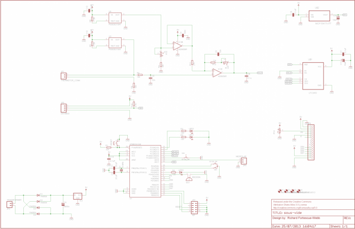
The design revolves around a control loop to keep the temperature constant in the water bath, this will probably involve a PID loop. The temperature of the water is sensed by either of the two sensors and the power to the appliance is modulated through an SSR. The schematic is shown below:
The circuit is based around an ATmega168, this means its compatible with the Arduino bootloader and makes the software a little easier. The schematic is fairly simple. Power comes in from a transformer and is rectified and regulated, all the AVR circuitry is standard. The only unusual part is the thermistor sense circuit. I based the design on an application note from TI – SLOA052. Essentially, there are two problems with the standard method of using a potential divider to measure a thermistor’s voltage drop: non-linearities are introduced and the thermistor may be subject to self heating. By using a current source to pass a very small current through the thermistor and measuring the resulting voltage, both problems can be avoided. The voltage across the thermistor is then amplified and offset to move it into the range of an ADC.
I ended up using an LTC2452 for the ADC. This is almost certainly overkill, and a 12-bit ADC could be used instead but the LTC2452 met my requirements and was a reasonable price. There are actually a couple of components which could be changed for cheaper / lower performance parts, the op-amp is likely better than it needs to be and the current source could be implemented discretely to lower the cost. Most of the parts were what I had on hand from previous sample orders.
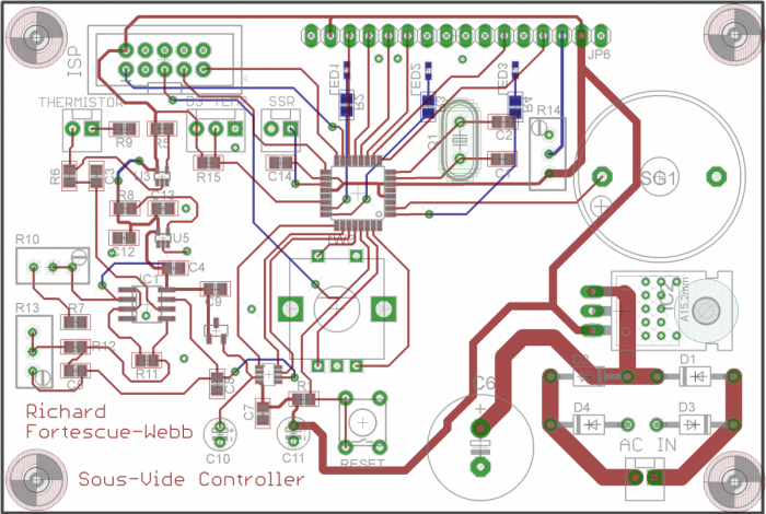
The PCB design was more rushed than I would have liked and as such I’ve already noticed a few mistakes, but I’ll detail those after I’ve built it up and tested it. I designed the board to mount directly under the lid of the box below the LCD. The rotary encoder is mounted on the top of the board and emerges through the lid. All the sensors are connected through headers since I’ll eventually be using sockets to connect them in to the box.
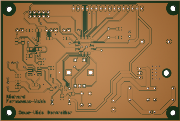
I used Mayhew Lab’s webGerber service to generate a render of the board with no soldermask or silkscreen.
All the files for the design are available on my github, feel free to share / modify / use them as you like.
